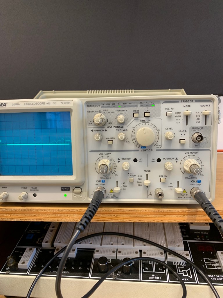
After turning on the oscilloscope, I set the two channels to Direct Current (DC) since we were dealing with a DC input. I made sure the x and y-xis were set to the middle so the sine wave we were looking at would be positioned in the center. The X-axis shows the time, and the Y-axis shows the voltage. Together, they show voltage in relation to time. I switched the mode to dual so we could see both channels and then use the potentiometer to fade between channels. When turning the potentiometer, we see the amplitude of one channel go down, while the amplitude the of the other channel increases. Turning the pot can show an output voltage of a minimum of 0% of the input voltage and a maximum of 100%. Then I set both of the Volts/Div knobs to .5V which determines the scale of the grid, meaning we would see half a volt for each little square on the screen. I turned the smaller Time/Div knobs all the way to the right until they clicked which allow you to fine tune the Volts/Div between the intervals on the big knob. I also set the Time/Div knob to .5 mS which means it takes half a mS for the wave to cross each division or square. Finally, I set the trigger mode to auto so that the threshold required for the signal to appear on the screen is 0. I connected the red probes to the positive side of the circuit and the black probes to ground.
