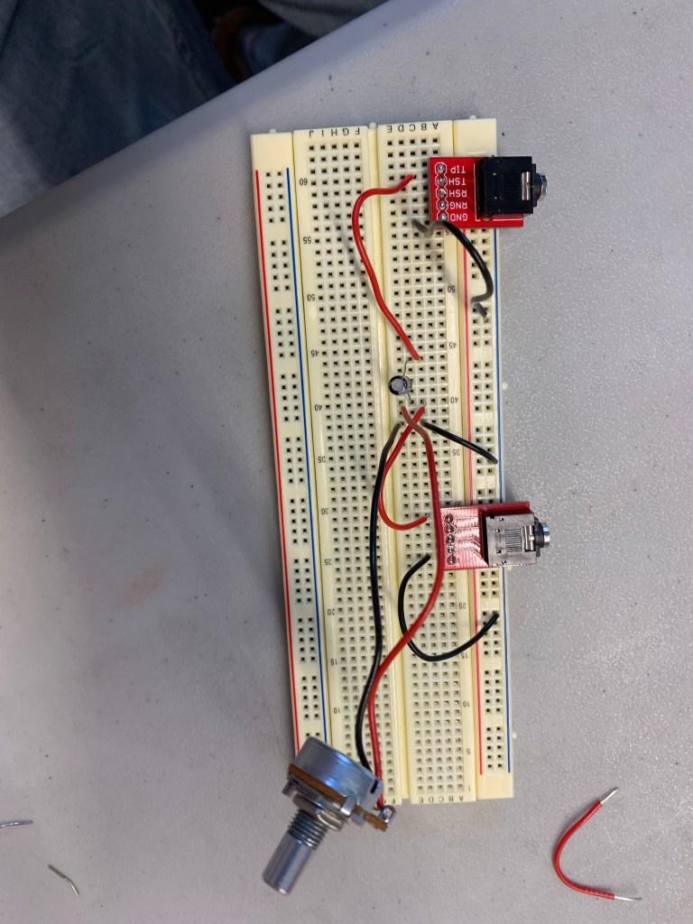
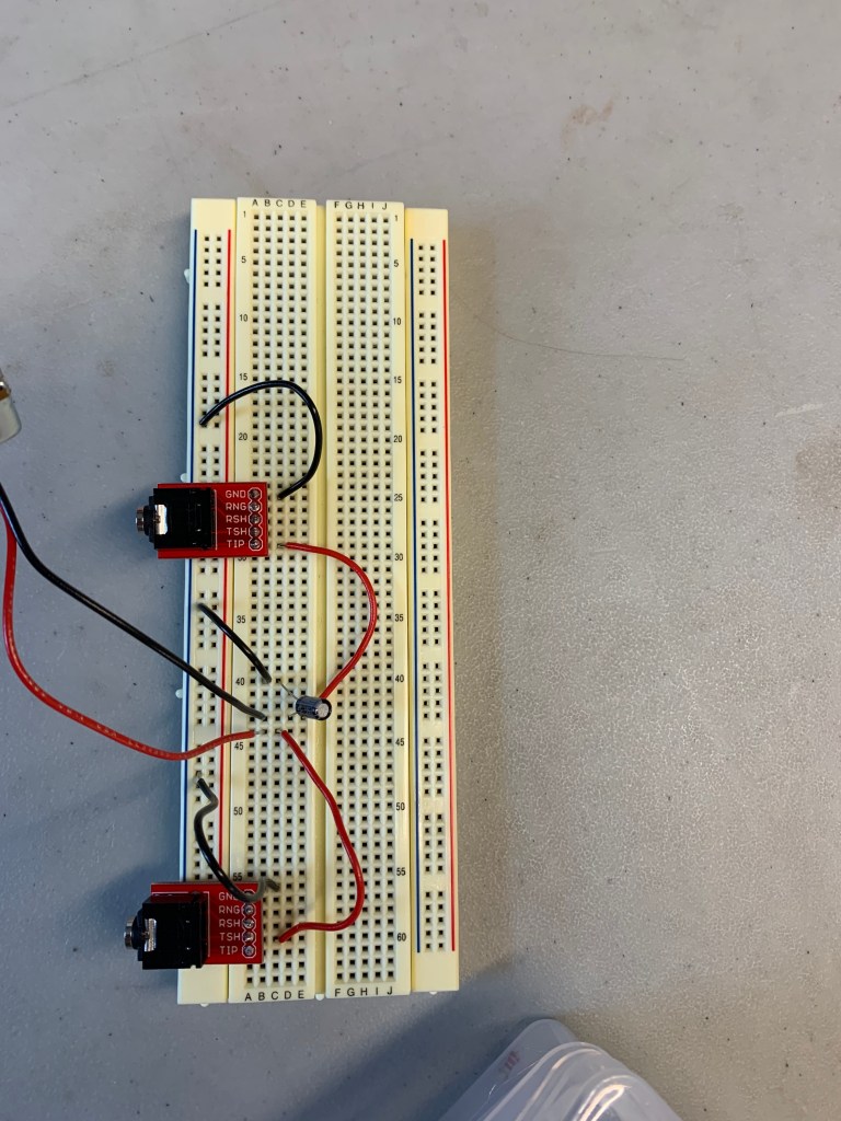
Breadboards
Breadboards have small metal clips under each hole which grab on to the copper wires that stick in to them. The metal clips are conductors which become charged when you connect a battery to the breadboard and the current flows through from positive to negative. However, the two halves have no connection to each other. You can use a breadboard to create a prototype design of a project. There is also a sticky back that allows you attach it to something.
Schematics
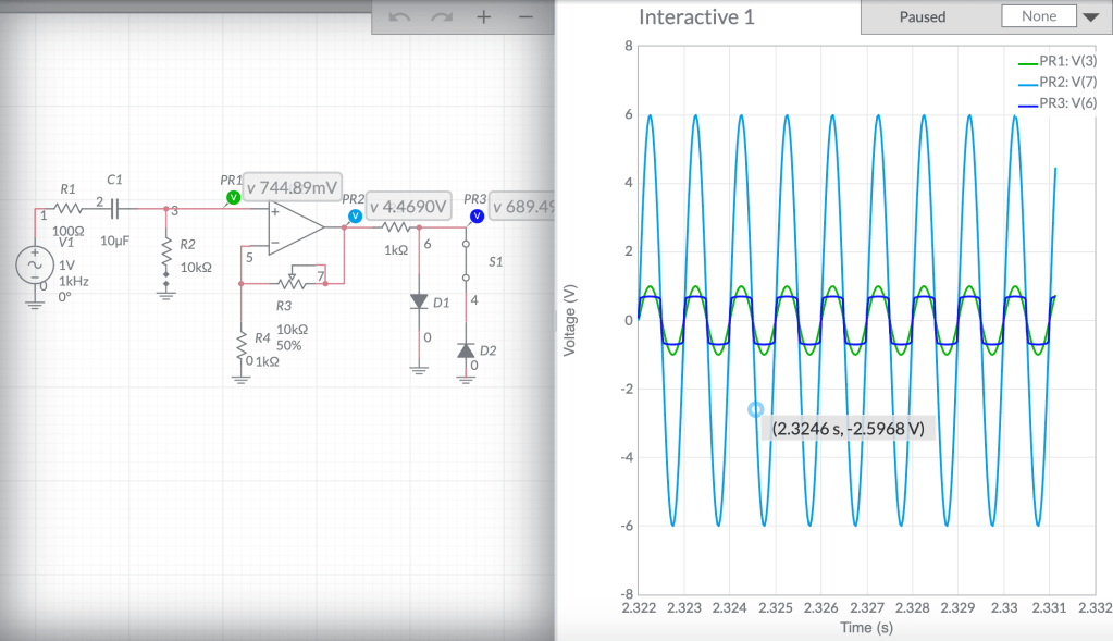
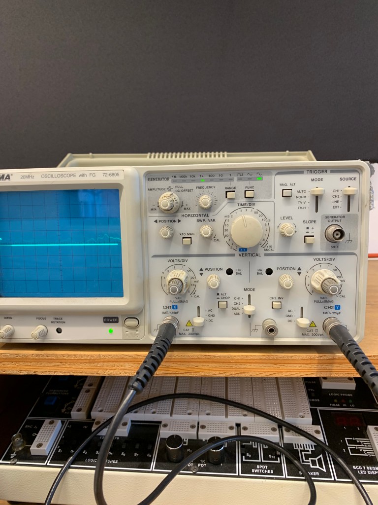
Multimeters
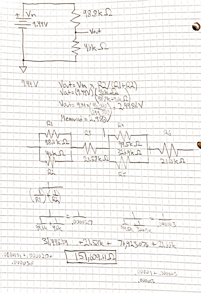
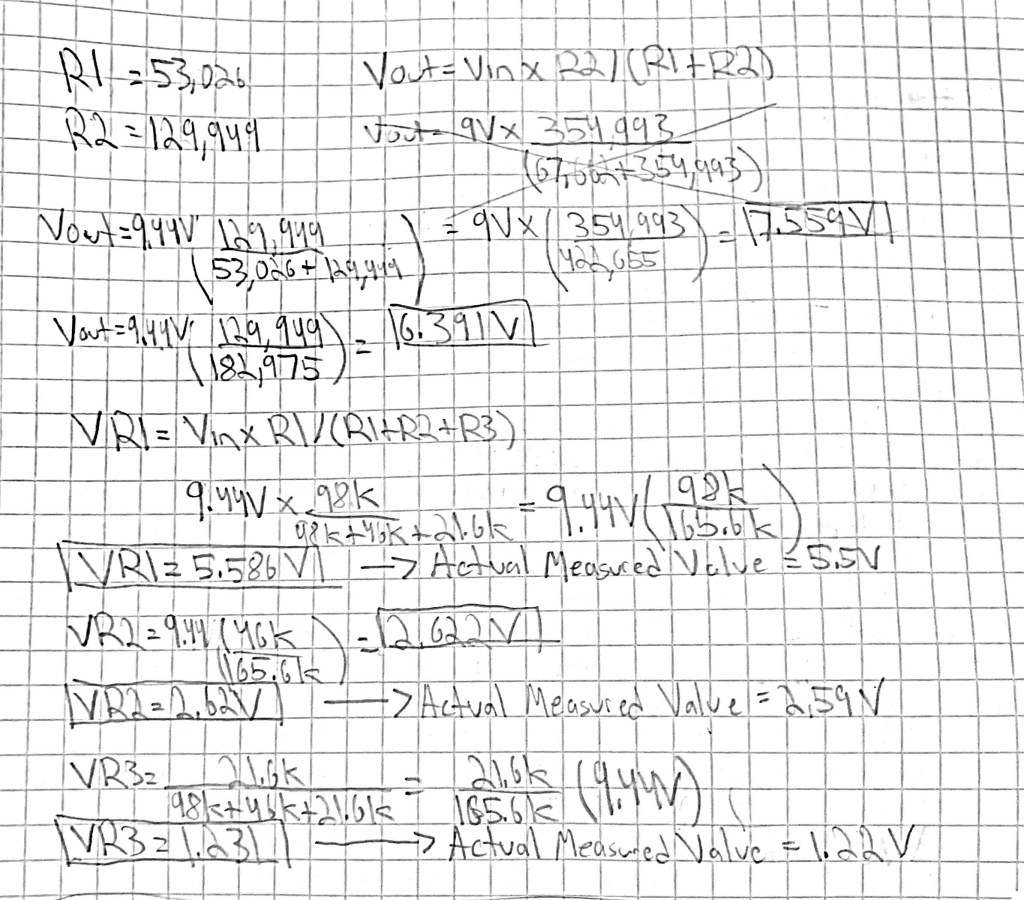
Multimeters are a tool that you can use to test the connectivity of a circuit. It can test the current, resistance, and voltage of a circuit. We used it to check the voltage of the batteries we were using. You can use it to troubleshoot your circuit, too. For example, by using the method of Nodal Analysis, you can check the voltage that each component of your circuit needs.
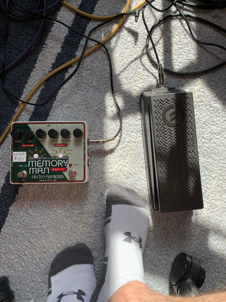
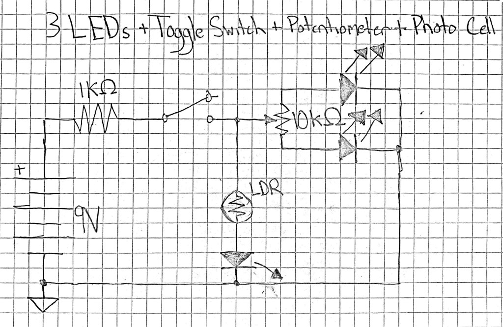
Final Project
Jacob Sandakly: The idea was very creative and there isn’t really anything else like it. It is also really cool how the microphone acts as mouthpiece and controls the volume of each breath
Connor Riley: I was actually very impressed with the quality of the distortion effect. It sounds like something I would actually want to use in one of my songs. It’s really cool how you can also control the low-pass filter with light or a knob.
Alexandra Dyan: The vibrato effect was super cool and made the synth sound 10 times better.